
Abstract
Conventional three-phase motor drives are widely used for humanoid joint actuators because they offer mature control methods, compact designs, and compatibility with established applications. However, they have no inherent alternative power path if a semiconductor switch, inverter leg, or motor phase becomes unavailable. Converter-level fault-tolerant architectures address this limitation by adding redundancy mainly to the power converter while keeping the conventional three-phase machine structure. The main options - switch-redundant, spare-leg, and four-leg architectures - use different approaches to achieve fault tolerance. They differ in fault coverage, post-fault capability, isolation requirements, semiconductor needs, and hardware overhead. Accordingly, converter-level fault tolerance should be evaluated by considering the required post-fault capability against the added isolation, current, thermal, and SWaP penalties. The design goal is to preserve the required actuator capability for a defined fault set with the lowest possible system-level overhead.
1 Introduction
Three-phase permanent-magnet motor (PMSM) drives are widely used in humanoid joint actuators because they provide reliable control of high torque density. However, a conventional three-phase inverter has no inherent alternative power path if a semiconductor switch, inverter leg, or motor phase becomes unavailable. As a result, the actuator may lose part or all of its controllable joint torque unless the drive includes protection, isolation, and reconfiguration mechanisms [1], [2].
Converter-side redundancy can add fault tolerance without major changes to the electric machine. This approach is useful when the three-phase motor is already fixed by electromagnetic design, manufacturing, packaging, or previous validation.
In this context, redundancy can preserve the electric motor. It adds alternative current paths or control degrees of freedom through auxiliary switches, a spare inverter leg, or a fourth neutral-connected leg. As shown in Fig. 1, these methods place redundancy at different points in the converter but keep the conventional three-phase machine with no change. They share the same goal of controlled operation, but use different reconfiguration methods.
Fig. 1 summarizes the three main converter-level fault-tolerant approaches: switch-redundant, spare-leg, and four-leg architectures. All three retain the conventional three-phase machine, but create fault-tolerant capability in different ways. Switch-redundant solutions use auxiliary switching and isolation paths. Spare-leg architectures add a replacement converter path. And four-leg converters add an independently controlled neutral-current path.
These differences directly affect actuator design. A switch-redundant architecture can limit changes to the main converter but may require additional isolation and protection hardware. A spare-leg architecture can directly replace a failed inverter leg, but its redundant power hardware remains unused during healthy operation. A four-leg inverter instead adds an independently controlled neutral-current path. This path supports operation under selected asymmetric faults rather than replacing a failed phase leg [1]. Therefore, the architectures should be compared based on fault coverage, usable post-fault capability, isolation requirements, current and thermal stress, and SWaP penalty.
For humanoid joint drives, this comparison is important because converter redundancy must fit within limited actuator space and thermal capacity. Added semiconductor devices, gate drivers, transfer switches, protection elements, conductors, and cooling hardware can increase mass, packaging effort, and integration complexity. Therefore, converter-level fault tolerance should be considered as an actuator-system design problem. And it should not be treated only as a modification of the inverter power stage.
The three architectures considered here - switch-redundant, spare-leg, and four-leg converters - add different types of converter-side redundancy. Their comparison addresses a central design question:
How much converter redundancy is needed to meet the required post-fault capabilities while keeping an acceptable level of system-level penalty?
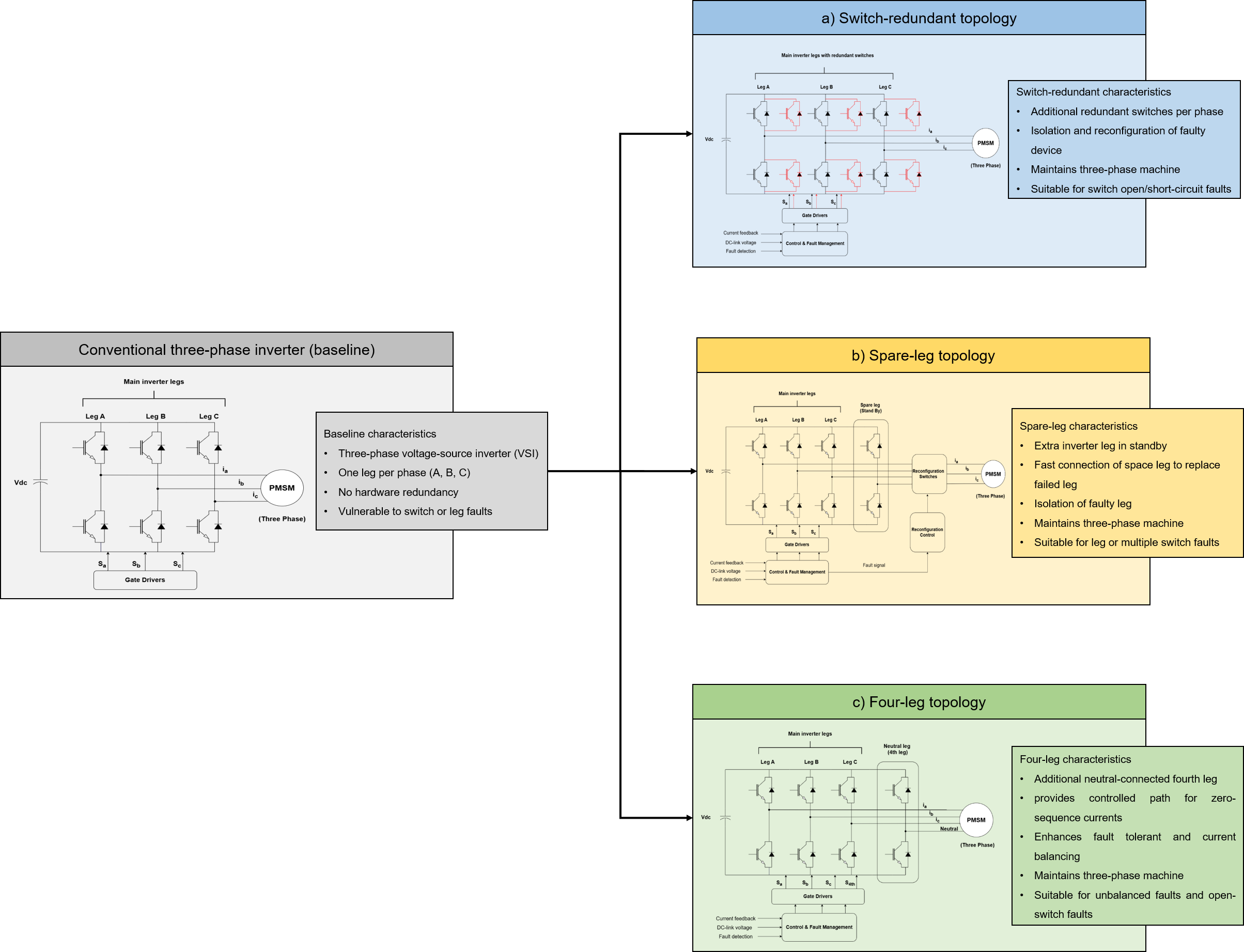
Fig. 1: Converter-level fault-tolerant architectures for three-phase joint drives. A conventional three-phase VSI is extended through three representative approaches: switch-redundant topology, spare-leg topology, and four-leg inverter. In all cases, the electric machine remains fundamentally three-phase while fault-tolerant capability is introduced primarily through converter-side redundancy and associated isolation mechanisms.
2 Conventional Three-Phase VSI as the Baseline
A conventional three-phase two-level voltage-source inverter has three phase legs and six active power switches. It uses the fewest number of power switches among different converter topologies in this article, and therefore, it serves as the reference for evaluating the added semiconductor rating and hardware overhead of fault-tolerant solutions.
The Silicon Overrating Cost Factor (SOCF) is used to compare semiconductor-rating overhead [1]. The conventional three-phase inverter is the baseline and is assigned SOCF = 1. SOCF is not the purchase cost of an inverter. Instead, it is a normalized measure of power-device voltage and current capability relative to the conventional three-phase baseline [1]. Accordingly, SOCF > 1 means that a topology needs greater weighted semiconductor voltage-current capability than the reference inverter. However, SOCF does not include factors such as PCB area, gate drivers, protection devices, contactors, connectors, sensors, cooling hardware, or manufacturing complexity.
The conventional three-phase inverter has no inherent redundant power path. Therefore, if one main power path becomes unavailable, continued controlled operation requires added isolation, changed electrical connections, or dedicated reconfiguration hardware. This limitation makes the six-switch inverter the minimum-hardware baseline for evaluating converter-level fault-tolerant architectures.
For humanoid joint actuators, this baseline represents more than a minimal fault-tolerant architecture. It provides a reference point for evaluating the additional mass, volume, thermal requirements, isolation complexity, and control effort introduced by other fault-tolerant topologies. Therefore, the design objective is not to maximize redundancy, but to determine whether the resulting increase in post-fault capability justifies the associated system-level penalty.
3 Switch-Redundant Architecture
A switch-redundant architecture adds fault tolerance through auxiliary switching and isolation paths around a conventional three-phase inverter. It does not require a full redundant inverter leg. The operating principle has two steps: fault isolation and converter reconfiguration. After the faulty path is identified and isolated, the remaining converter resources and auxiliary switches create a controllable post-fault operating state.
As shown in Fig. 2, the conventional three-phase inverter operates normally during healthy operation. The added switching and protection paths remain available for fault handling. After a fault affects one converter path, that section is isolated. The converter is then reconfigured to maintain controlled current through the remaining healthy paths.
Post-fault capability depends strongly on fault type, fault location, and the available reconfiguration method. For a single-phase open-circuit fault, torque production can continue after isolating the unavailable current path. The current references of the healthy phases are then adjusted. In the switch-redundant configuration analyzed in [1], this condition produced an SOCF of 1.29. The same reference also evaluates the Fault Power Rating Factor (FPRF) for the same topology. In more details FPRF is the ratio between maximum output power in post-fault operation to the maximum output power in normal conditions. For switch redundant topology the FPRF is 0.5 [1].
The obtained results presented in [1] indicate that switch-redundant architectures can provide selected fault-tolerant operation with limited additional semiconductor overhead. However, the achievable post-fault capabilities depend on the fault condition and may remain below the healthy-state level for a certain fault type. Therefore, redundancy count alone does not show the effectiveness of this architecture. An auxiliary switch or alternative current path is useful only if the original fault can first be isolated. This is especially important for semiconductor short-circuit faults, because the failed device may keep an uncontrolled electrical path active. Depending on the design, additional protection and isolation elements may be needed before safe post-fault operation is possible [1], [2].
This leads to a key design principle:
Redundant switching capability is effective only when combined with reliable fault isolation.
From an actuator-integration perspective, switch redundancy is attractive because it can retain the conventional three-phase motor and most of the inverter structure. However, limited changes to the main power stage do not mean low implementation overhead. Auxiliary switches, protection components, gate-drive circuits, added interconnections, and fault-routing elements increase PCB area, thermal load, packaging complexity, and the number of possible failure points.
Therefore, the main advantage of switch redundancy is not maximum post-fault capability. It is the ability to add targeted fault tolerance with limited changes to an existing three-phase drive. This approach is most suitable when the target fault set is well defined, some reduction in post-fault capability is acceptable, and retaining the original motor and converter structure is the main design goal.
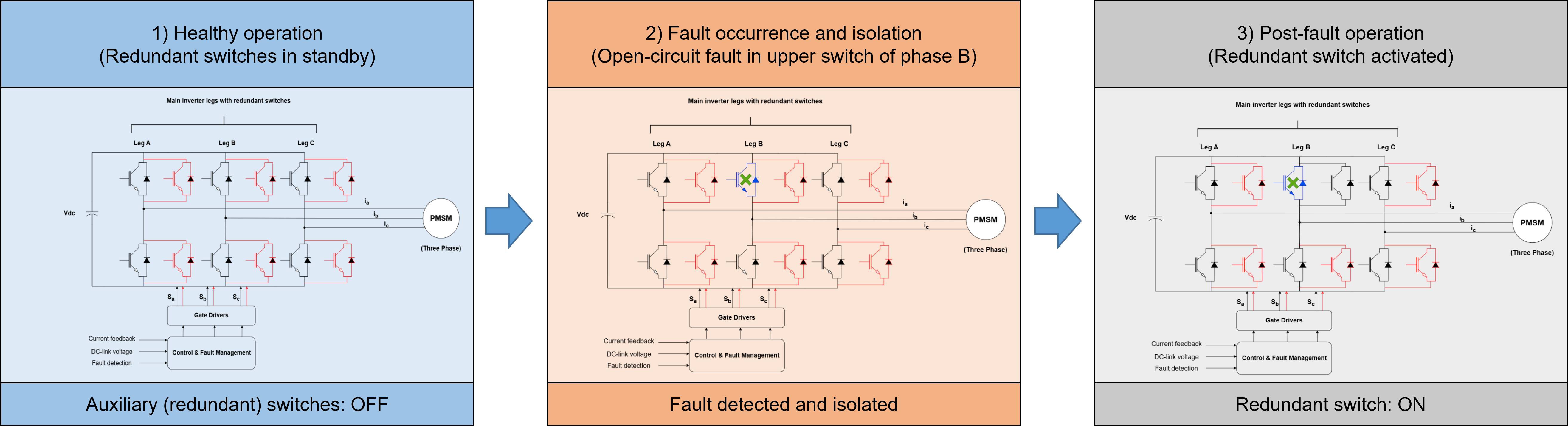
Fig. 2: Switch-redundant converter architecture and post-fault reconfiguration principle. During healthy operation, the conventional three-phase inverter operates normally while auxiliary switching and isolation paths remain inactive. After fault detection, the faulty converter path is isolated and the remaining converter resources are reconfigured to maintain controllable operation of the three-phase machine.
For humanoid joint drives, three questions should guide the evaluation:
First, can the target fault be isolated reliably?
Second, can the remaining electrical paths provide the required post-fault torque and speed?
Third, can the added protection and reconfiguration hardware fit within the actuator’s electrical, thermal, and SWaP limits?
4 Spare-Leg Three-Phase Drive
A spare-leg architecture adds converter-level fault tolerance by using a complete, redundant inverter leg. This leg can replace a failed phase leg after fault detection and isolation. Unlike switch-redundant designs, which use auxiliary paths to reconfigure the existing converter, spare-leg designs provide a dedicated replacement power path. They also keep the conventional three-phase motor.
Fig. 3 shows the operating principle. During healthy operation, the redundant inverter leg remains inactive. After a converter fault is detected and isolated, the spare leg connects to the affected phase and restores a controllable three-phase power path.
The main advantage of this architecture is that it can restore a complete three-phase converter path after a phase-leg failure. After fault detection and isolation, the spare leg connects to the affected motor phase. Therefore, continued operation does not rely only on redistributing current through the remaining healthy phases. The failed power path is replaced rather than compensated by a degraded operating mode.
In the three-phase comparison in [1], the analyzed spare-leg topology achieved an FPRF of 1.0 under the defined converter fault conditions. Under the evaluation method used there, this equals the healthy-state reference capability. However, this performance required a higher semiconductor rating, with an SOCF of 2.33 relative to the conventional six-switch inverter [1].
These values apply to the topology, fault cases, and rating assumptions analyzed in [1]. They do not mean that every spare-leg design gives the same post-fault performance. Instead, they show that a dedicated redundant inverter leg can provide high converter-level fault tolerance by directly replacing a failed power path. This capability requires additional installed hardware.
The hardware penalty includes more than the redundant semiconductors. A practical spare-leg design also needs gate-drive circuits, isolation elements, protection coordination, electrical connections, and mechanical and thermal integration. As a result, actuator-level impact depends on factors such as semiconductor count, cooling requirements, packaging volume, and system complexity.
For humanoid joint drives, this trade-off requires careful evaluation. A key advantage is that the existing three-phase machine can remain unchanged in its electromagnetic design, winding arrangement, and manufacturing process. However, the added converter hardware increases actuator overhead and leaves less space for other components within the joint.
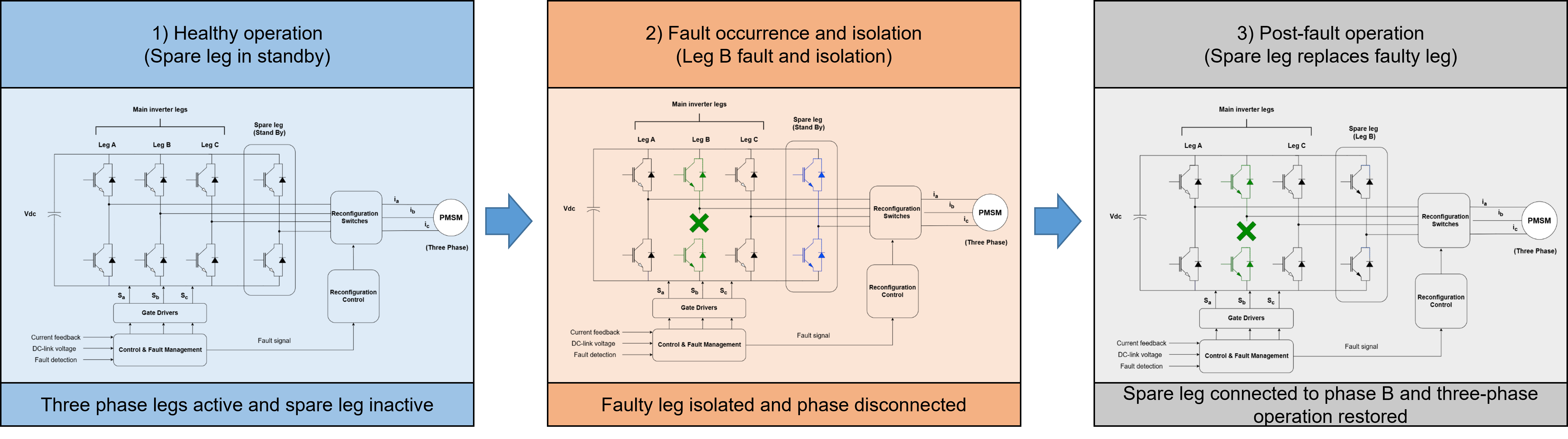
Fig. 3: Spare-leg converter architecture and post-fault reconfiguration principle. During healthy operation, the redundant inverter leg remains inactive. After fault detection and isolation of a failed phase leg, the spare leg is connected to the affected phase to restore a controllable three-phase converter path.
Fault-domain independence is another important factor. The active and spare legs may still share the same DC link, controller unit, cooling system, or communication interface. Therefore, effective redundancy requires limits on common dependencies between the active and spare channels.
Therefore, the spare-leg architecture is most suitable when high converter-level post-fault capability is required. It is also suitable when motor changes are undesirable and the actuator can accommodate the added converter hardware. Compared with switch-redundant designs, it provides a more direct recovery path for inverter-leg failures, but with higher hardware and system complexity.
5 Four-Leg Inverter
A four-leg inverter adds converter-level fault tolerance through an additional inverter leg connected to the motor neutral point. Unlike a spare leg, which is reserved to replace a failed converter leg, the fourth leg provides a controlled current path. This added path increases the available electrical degrees of freedom during asymmetric fault conditions.
Fig. 4 shows the operating principle. During healthy operation, the converter works as a conventional three-phase inverter, while the neutral-connected leg remains available for fault handling. After a phase or converter fault, the fourth leg can control the neutral current and support continued operation of the healthy phases.
The main advantage of this architecture is that it can manage asymmetric electrical conditions without directly replacing a failed phase leg. By controlling the neutral current, the converter can compensate for the imbalance caused by selected open-circuit faults. As a result, the remaining healthy phases can continue to produce controllable torque.
In the three-phase comparison in [1], the analyzed four-leg topology achieved an FPRF of 0.58 and an SOCF of 1.58 under the defined fault conditions. These values apply only to the topology, fault cases, and rating assumptions used in that study. They should not be treated as universal values for all four-leg converters [1].
These results place the four-leg architecture between the switch-redundant and spare-leg approaches. It adds converter hardware and control capability but does not directly replace a failed phase leg. Instead, it supports controlled post-fault operation by adding a current path that manages fault-induced asymmetry.
The key design issue is the current rating of the additional leg. During fault operation, the neutral-leg current can differ significantly from the normal phase currents. This occurs because the fourth leg compensates for the fault-induced imbalance. Therefore, semiconductor selection, conductor sizing, and thermal design should consider post-fault conditions. They should not be based only on the normal operating point.
Compared with spare-leg designs, a four-leg converter can reduce the need for phase-transfer mechanisms because the added leg is already part of the converter. However, it does not provide the same fault coverage. Post-fault capability still depends on the fault type, control strategy, and electrical limits of the machine and converter.
For humanoid joint drives, the four-leg inverter offers a compromise between added converter capability and hardware overhead. It keeps the conventional three-phase machine and adds one control degree of freedom. Therefore, it is attractive when asymmetric open-circuit faults dominate the target fault set and moderate post-fault capability is sufficient.
Like other converter-level fault-tolerant architectures, the fourth leg does not automatically create an independent fault domain. Shared resources such as the DC- link, controller, auxiliary supply, cooling system, and communication interface can still create common-cause dependencies. Therefore, effectiveness depends on both the added current path and the overall fault-isolation strategy.
The four-leg architecture is therefore suitable when the required post-fault capability matches its main function: maintaining controlled operation under selected asymmetric faults rather than replacing every failed converter path.
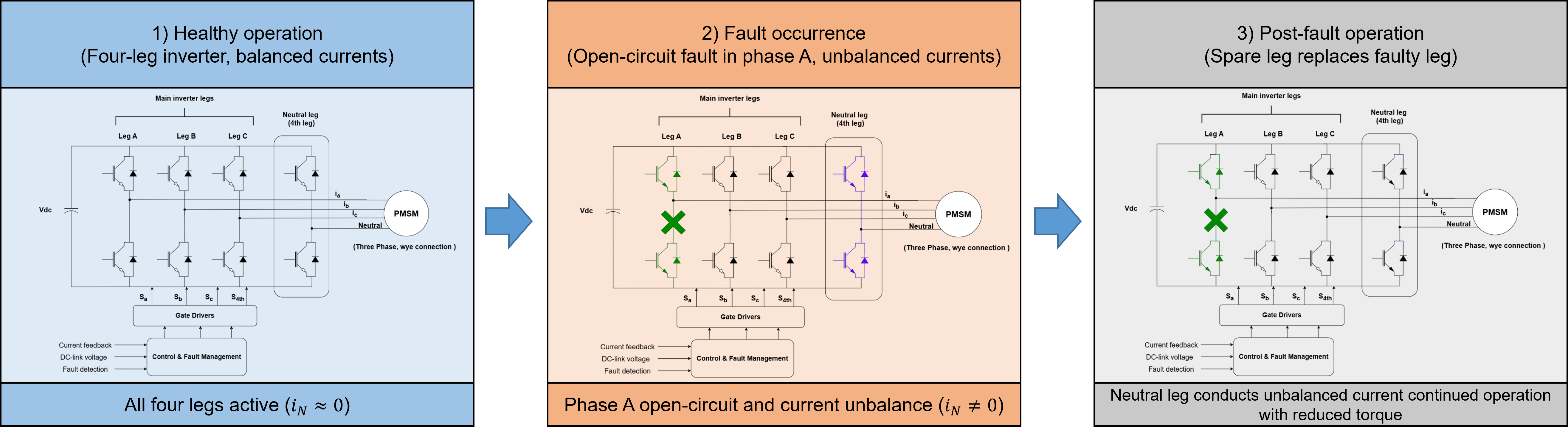
Fig. 4: Four-leg inverter architecture and post-fault current-path control. The additional inverter leg is connected to the motor neutral and provides an independently controlled current path during asymmetric fault conditions, enabling continued operation of the remaining healthy phases.
6 Converter-Level Architecture Comparison
The three converter-level fault-tolerant architectures discussed here share one goal: maintain controllable actuator operation after selected electrical faults while keeping the conventional three-phase machine. However, they use different redundancy mechanisms. As a result, they differ in post-fault capability, hardware overhead, and implementation complexity.
A switch-redundant architecture adds auxiliary switching and isolation paths to the conventional inverter. Its main advantage is the limited change to the power stage. However, post-fault capability depends strongly on the fault type and the quality of fault isolation. In the configuration analyzed in [1], it achieved an FPRF of 0.5 and an SOCF of 1.29 under the defined fault condition.
A spare-leg architecture instead provides a dedicated replacement path for a failed inverter leg. This can give higher post-fault capability because the failed converter path is replaced directly rather than compensated by degraded operation of the remaining phases. In [1], the analyzed spare-leg topology achieved an FPRF of 1.0 and an SOCF of 2.33 under the considered converter faults.
A four-leg inverter adds a controlled current path through a neutral-connected leg. Rather than replacing a failed phase leg, it adds electrical freedom for controlled operation under selected asymmetric faults. In [1], the analyzed four-leg topology achieved an FPRF of 0.58 and an SOCF of 1.58 for the evaluated fault case.
Table 1 summarizes the main architectural differences, redundancy methods, and design trade-offs. The comparison shows that converter-level fault tolerance depends not only on added hardware. It also depends on how well that hardware provides useful post-fault actuator capability.
The numerical values in Table 1 apply to the specific topologies, fault assumptions, and evaluation methods used in the referenced comparison. Therefore, they should be treated as representative results, not universal performance values.
The comparison shows a clear design principle: higher post-fault capability generally requires more hardware, higher semiconductor rating, and more complex fault management. However, the architecture with the most redundancy is not necessarily the best choice for a humanoid joint actuator.
Architecture selection depends on the target fault set, acceptable degraded performance, thermal capability, packaging limits, and available SWaP budget. If preserving the existing three-phase drive is the main goal, a switch-redundant solution may provide a suitable balance between added capability and complexity. If near-nominal capability is required after a phase-leg failure, the added hardware of a spare-leg architecture may be justified. If asymmetric open-circuit faults dominate the target fault set, a four-leg inverter may provide a balanced compromise.
In addition, architecture selection must consider fault-domain independence. Added converter paths provide effective protection only when shared resources and common-cause failures are properly evaluated. A redundant path that shares a vulnerable DC link, controller, auxiliary supply, or thermal path may not provide the expected system resilience.
Therefore, converter-level fault tolerance should follow the principle of minimum sufficient redundancy. The selected architecture should provide the required fault coverage and post-fault capability with the lowest possible added converter complexity. It should also remain within the actuator’s electrical, thermal, mechanical, and SWaP limits.
Table 1: Comparison of converter-level fault-tolerant architectures.
7 Conclusion
Converter-level fault tolerance is a practical way to improve the resilience of humanoid joint drives while keeping the conventional three-phase motor. By placing most redundancy in the power converter, fault-tolerant capability can be added without major changes to the machine electromagnetic design, winding structure, or established manufacturing process.
The three architectures discussed here - switch-redundant, spare-leg, and four-leg converters - use different methods for post-fault operation. Switch-redundant designs isolate faults and reconfigure existing converter resources. Spare-leg designs directly replace a failed inverter leg and can provide higher post-fault capability, but require more hardware. Four-leg converters add a controlled current path that supports operation under selected asymmetric faults.
This comparison shows that fault tolerance should not be judged only by the amount of added redundancy. The key question is whether the added converter resources provide the required post-fault capability within the actuator’s electrical, thermal, mechanical, and SWaP limits. Higher redundancy can improve fault coverage, but it also increases semiconductor needs, protection complexity, packaging demands, and possible common-cause dependencies.
Therefore, the best converter architecture for a humanoid joint actuator is not the one with the most redundancy. It is the one that provides the minimum sufficient redundancy for the target fault set and post-fault requirements. This choice requires a system-level assessment of fault isolation, current and thermal margins, duration of degraded operation, and independence of redundant resources.
Converter-level redundancy is only one part of the broader fault-tolerant drive design space. If converter-side solutions cannot meet the required post-fault capability, redundancy can also be added within the electric machine.
References
[1] B. A. Welchko, T. A. Lipo, T. M. Jahns, and S. E. Schulz, “Fault tolerant three-phase AC motor drive topologies: A comparison of features, cost, and limitations,” IEEE Transactions on Power Electronics, vol. 19, no. 4, pp. 1108–1116, Jul. 2004.
[2] S. Rahimpour, O. Husev, D. Vinnikov, N. V. Kurdkandi, and H. Tarzamni, “Fault management techniques to enhance the reliability of power electronic converters: An overview,” IEEE Access, vol. 11, pp. 13432–13446, 2023.