Knowledge Base
Converter-Level Fault-Tolerant Architectures for Humanoid Joint Drives

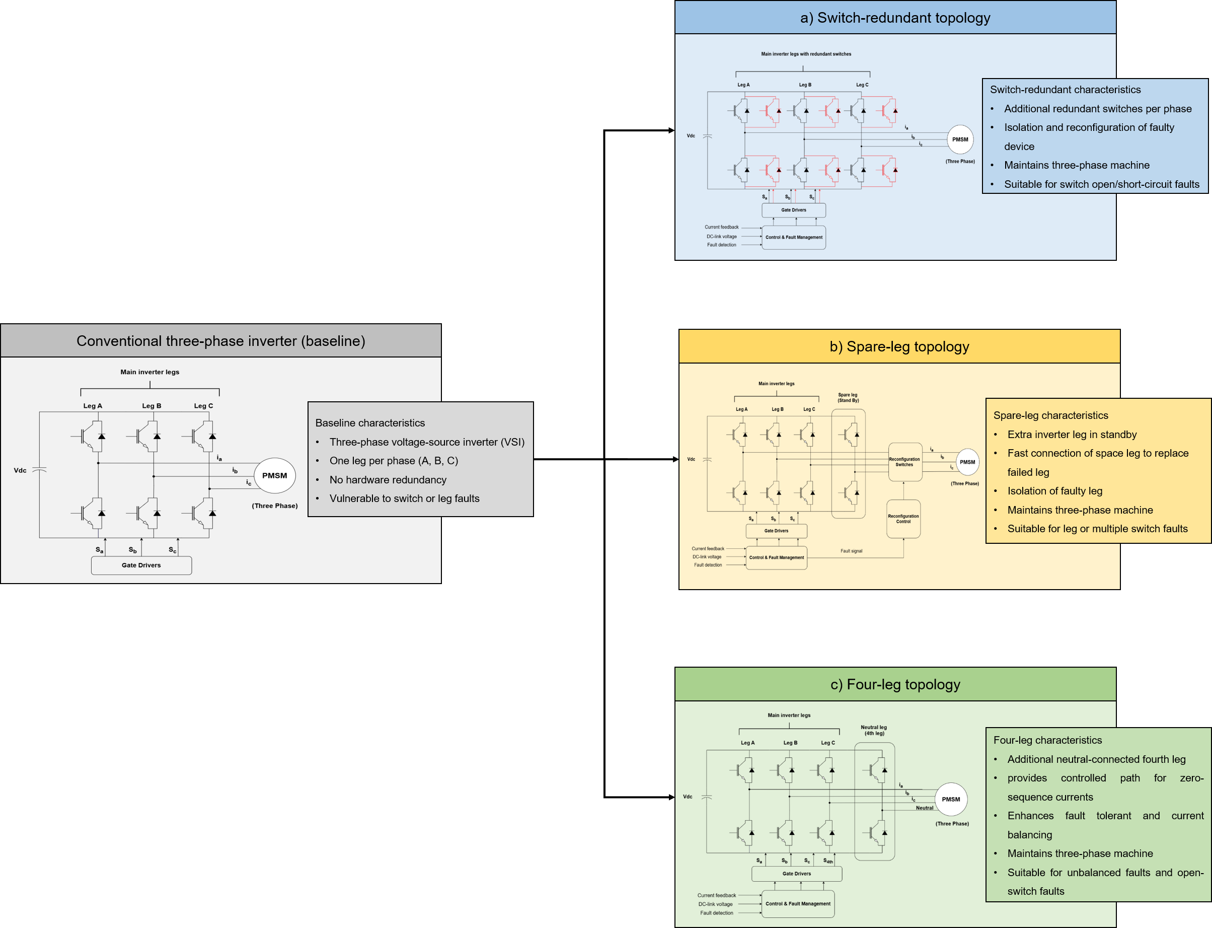
Conventional three-phase motor drives are widely used for humanoid joint actuators because they offer mature control methods, compact designs, and compatibility with established applications. However, they have no inherent alternative power path if a semiconductor switch, inverter leg, or motor phase becomes unavailable. Converter-level fault-tolerant architectures address this limitation by adding redundancy mainly to the power converter while keeping the conventional three-phase machine structure. The main options - switch-redundant, spare-leg, and four-leg architectures - use different approaches to achieve fault tolerance. They differ in fault coverage, post-fault capability, isolation requirements, semiconductor needs, and hardware overhead. Accordingly, converter-level fault tolerance should be evaluated by considering the required post-fault capability against the added isolation, current, thermal, and SWaP penalties. The design goal is to preserve the required actuator capability for a defined fault set with the lowest possible system-level overhead.
Fault-Tolerant Electric Drives for Humanoid Robots What Must a Joint Drive Still Deliver After a Fault?
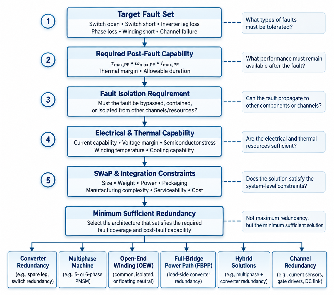
Electric joint drives areamong the most critical subsystems in humanoid robots. Each actuator integratesthe electric machine, power converter, sensors, embedded control, andmechanical transmission within strict mass and volume limits. When a fault occurs,the key engineering question is not only whether the motor can still rotate. Itis also what actuator capabilities remain after the fault.Accordingly, arequirement-driven framework is used for fault-tolerant electric-drive designin humanoid joints. It begins by defining the target fault set and the requiredpost-fault capabilities. The framework distinguishes fault tolerance fromreliability and examines the main drive-level fault classes, with emphasis onthe different requirements in the case of each fault. Key design factorsinclude the post-fault torque-speed characteristics, current and thermalmargins, fault isolation methodology, and Power constraints. Instead ofmaximizing hardware redundancy, the approach identifies the minimum redundancyneeded to maintain the specified post-fault capabilities within acceptableelectrical, thermal, and system-level limits.
.svg)
Field-Oriented Control of Permanent Magnet Synchronous Motors: Principles and Functional Analysis
Field-Oriented Control (FOC) enables Permanent Magnet Synchronous Motor (PMSM) drives to achieve a DC-like, decoupled control structure by independently regulating torque and flux producing current components in a synchronously rotating reference frame aligned with the rotor magnetic field. Unlike induction machines, where rotor flux must be established through stator excitation and slip frequency tracking, PMSMs inherently provide excitation through permanent magnets. Consequently, the d-axis current influences the resultant air gap flux linkage and, depending on the machine topology, may also contribute to torque optimization. In surface mounted PMSMs (SPMSMs), the d-axis current is typically regulated near zero under nominal operating conditions (idref ≈ 0), whereas in interior PMSMs (IPMSMs), a nonzero negative d-axis current is often employed to exploit rotor saliency for Maximum Torque Per Ampere (MTPA) operation and flux weakening. The measured three phase stator currents are transformed into the rotating d–q reference frame using Clarke and Park transformations, where the q-axis current primarily governs electromagnetic torque production. This representation enables fast dynamic response through conventional PI current regulators, optionally enhanced with cross-coupling compensation. Accurate electrical angle information, θe, is obtained from a position sensor (e.g., encoder or resolver) or a sensorless estimation algorithm to maintain proper reference frame alignment. The resulting voltage commands are transformed back to the stationary reference frame via the inverse Park transformation and applied to the inverter using Space Vector Pulse Width Modulation (SVM), enabling efficient synthesis of the commanded stator voltages. The resulting control architecture provides high torque bandwidth, low torque ripple, high efficiency, and reliable operation over a wide speed range, including MTPA and flux-weakening regions in high-performance PMSM drive systems.
Sinusoidal Pulse Width Modulation (SPWM) vs Space Vector Modulation (SVM)
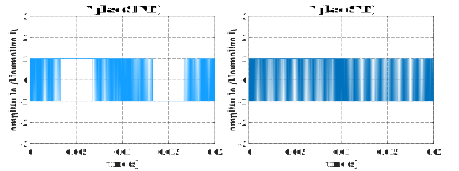
The utilization of Space Vector Modulation (SVM) in three-phase inverters is essential due to its superior DC-link voltage utilization compared to the conventional Sinusoidal Pulse Width Modulation (SPWM) method. Unlike SPWM, which is restricted to a pure sinusoidal reference, SVM inherently and intentionally injects a third-order harmonic component into the phase voltages through optimal management of switching vectors. This component is effectively eliminated from line-to-line voltages due to their differential nature, thereby overcoming voltage amplitude constraints within the linear modulation region. This structural refinement of the voltage reference extends the linear modulation range by approximately 15% compared to traditional SPWM approaches.
.svg)
Emulating DC Motor Control in AC Induction Drives Using Field-Oriented Control (FOC)
Field-Oriented Control (FOC) transforms the control architecture of Induction Motors (IM) to emulate the decoupled dynamics of a separately excited DC motor. While DC motors naturally separate flux and torque through orthogonal windings, IMs feature inherently coupled, time-varying stator currents. FOC resolves this coupling by utilizing Clarke and Park transformations to project three-phase currents onto a synchronously rotating d-q reference frame aligned with the rotor flux. Within this coordinate system, the d-axis current regulates magnetization while the q-axis current independently controls electromagnetic torque, allowing for the use of standard PI regulators. Implementation on IMs requires precise rotor flux angle estimation, achieved by integrating the sum of the measured rotor speed and the estimated slip speed. Furthermore, feedforward decoupling compensation is integrated to mitigate cross-coupling effects at high speeds, and Space Vector Pulse Width Modulation (SVPWM) optimizes DC-bus utilization. This decoupling strategy ensures rapid dynamic response, minimized torque ripple, and maximum drive efficiency across the full speed range.