
Abstract
Electric joint drives are among the most critical subsystems in humanoid robots. Each actuator integrates the electric machine, power converter, sensors, embedded control, and mechanical transmission within strict mass and volume limits. When a fault occurs, the key engineering question is not only whether the motor can still rotate. It is also what actuator capabilities remain after the fault.
Accordingly, a requirement-driven framework is used for fault-tolerant electric-drive design in humanoid joints. It begins by defining the target fault set and the required post-fault capabilities. The framework distinguishes fault tolerance from reliability and examines the main drive-level fault classes, with emphasis on the different requirements in the case of each fault. Key design factors include the post-fault torque-speed characteristics, current and thermal margins, fault isolation methodology, and Power constraints. Instead of maximizing hardware redundancy, the approach identifies the minimum redundancy needed to maintain the specified post-fault capabilities within acceptable electrical, thermal, and system-level limits.
1 Introduction
Humanoid robots place demanding requirements on electric joint drives. These drives must provide high torque density, fast dynamic response, accurate torque control, and thermal robustness within a tight mechanical space. In addition, humanoid actuators operate in a floating-base mechanical system. Therefore, the available joint capability directly affects robot motion feasibility, robot mechanical balance recovery, and overall robot performance.
Fig. 1 shows the functional structure of a humanoid joint drive. The actuator is treated as an integrated electromechanical system that includes power electronics, the electric machine, sensors, embedded control, and mechanical transmission. This system-level view is important because a fault in one domain can directly affect the performance and safety of the complete actuator.
Modern humanoid actuators show a strong link between electrical and mechanical requirements. For example, the lower-limb actuators of the Mithra humanoid were designed around robot performance, mechanical design limits, and safety requirements [1]. Similarly, the MIT humanoid uses actuator modules with different torque-speed characteristics and transmission ratios based on their location and role in the robot [2].
Together, these examples show that electric-drive design must consider the joint's mechanical structure, dynamic requirements, and control objectives. This coupling becomes more important when fault tolerance is added to the list of requirements.
Several factors can help an actuator continue the operation after the fault. Good examples of such factors can be Extra inverter switches, redundant converter legs, independent winding sets, sensors, isolation circuits, or converter channels. However, adding redundancy to the robot can also increase semiconductor count, wiring complexity, cooling needs, control effort, manufacturing complexity, and actuator mass. In humanoid robots, hardware location also matters because added mass in distal limbs can increase reflected inertia and reduce dynamic performance [1]. Therefore, fault-tolerant actuator design should not aim to maximize redundancy. Instead, it should identify the minimum redundancy needed to preserve the required joint capability for the faults relevant to the application. This requires defining both the faults to be tolerated and the controllable actuator capability that must remain after a fault.
Accordingly, two basic design questions should be answered before selecting a fault-tolerant architecture:
1. Which faults must the drive tolerate?
2. And, what actuator capability must remain available after those faults occur?
The answers to the above two questions define the required fault coverage, post-fault performance, and acceptable hardware penalty for the selected architecture.
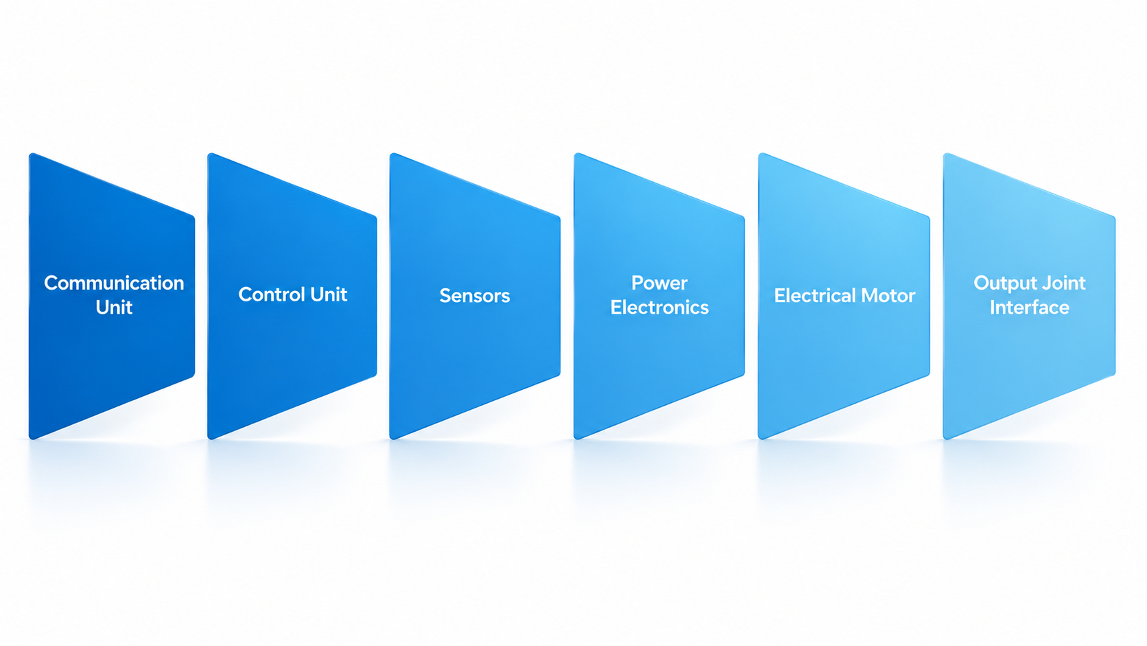
Fig. 1: Functional representation of a humanoid joint drive. The actuator is treated as a coupled electromechanical system that includes the DC interface, power converter, electric machine, sensors, embedded control, and mechanical transmission. All of these aspects should be considered in fault-tolerant design of a robot actuator.
2 Fault Tolerance Begins with the Fault Definition
An electric joint drive has several possible fault domains. For example, actuator faults can occur in power semiconductor devices, motor windings, sensors, the DC interface, the embedded controller, electrical connections, or the communication path.
In general, PMSM drive faults can be divided into three categories namely electric machine faults, power converter faults, and sensor faults [3]. In addition, converter-level fault-management studies emphasize protection, isolation, and hardware reconfiguration [4].
The most relevant electrical fault classes include:
● circuit failure of a semiconductor switch,
● Short-circuit failure of a semiconductor switch,
● Loss of an inverter leg,
● Motor winding open circuit fault,
● Motor winding short circuit,
● Loss of a complete converter or more than one motor winding.
Sensor and controller faults also affect actuator controllability. However, these faults are generally addressed through analytical redundancy and supervisory control rather than modifications to the main power topology [3]. These faults are not equivalent. A topology that tolerates one fault class may offer little or no protection against another. Therefore, the term fault-tolerant drive is incomplete unless the target fault set is clearly defined.
2.1 Open-Circuit Faults
An open-circuit fault removes an intended current path. Depending on the architecture, it may result from an open semiconductor device, the loss of an inverter leg, or the disconnection of a complete motor phase.
In multiphase machines, a main fault-tolerant mechanism is to redistribute current among the remaining healthy phases. The remaining electrical degrees of freedom can reconstruct the rotating magnetomotive force and recover part or all of the required torque after a phase is lost [5].
Converter-side redundancy offers a different solution. Instead of redistributing current among extra motor phases, redundant switches or inverter legs provide an alternative power path. For similar converter fault classes, three-phase fault-tolerant topologies can retain very different levels of post-fault power. Therefore, topology selection strongly affects the remaining drive capability [6].
Thus, even for open-circuit faults, architecture selection depends on whether fault tolerance is provided mainly by converter redundancy or machine-phase redundancy.
2.2 Short-Circuit Faults
Short-circuit faults create a different problem because the faulty element can remain electrically active.
A shorted power semiconductor can cause current to rise rapidly and usually requires protection and isolation before post-fault control can begin [4]. Therefore, a common fault-management goal is to where possible, convert it into a controllable open-circuit condition.
A short-circuited PMSM winding creates a more fundamental challenge because permanent-magnet excitation cannot be switched off. As long as the rotor moves, the magnets can induce an electromotive force in the shorted winding. This can produce current, heating, and disturbance or braking torque [7]. Fig. 2 shows the key differences between an open-circuit fault, where a current path is lost, and a short-circuit fault, where the fault can remain electrically active.
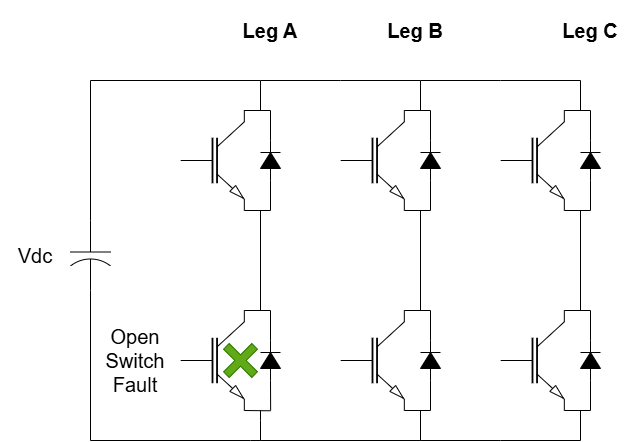
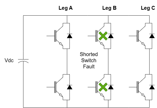
Fig. 2: Conceptual difference between open-circuit and short-circuit fault tolerance. An open-circuit fault removes an intended current path and may be handled by current redistribution or an alternative converter path. A short-circuit fault can remain electrically active and may require rapid isolation and machine-level measures to limit fault current and propagation.
For this reason, fault-tolerant permanent-magnet machines may require sufficient self-inductance, low mutual coupling, and electrical, magnetic, thermal, and physical separation between fault domains [7].
A drive architecture should therefore be evaluated separately for its ability to continue operation after losing a current path and its ability to contain an electrically active short-circuit fault.
3 Defining Post-Fault Actuator Capability
A binary Healthy/Faulty status does not fully describe a fault-tolerant actuator. After a fault, the actuator may remain controllable, but its maximum operational ratings may change. Therefore, stating that a drive continues operating is not enough for actuator design or robot-level control. A more useful description is the remaining post-fault operating envelope.
For design purposes, this envelope can be represented conceptually by:
C_PF={τ_(max,PF),ω_(max,PF),I_(max,PF),Θ_PF,t_allow } (1)
Where τ_(max,PF) is the available post-fault torque, ω_(max,PF) is the available speed range, I_(max,PF) represents the permissible post-fault current,Θ_PF represents the thermal state or thermal margin, and t_allow represents the time for which the specified operating condition can be maintained. Equation (1) is not an industrial standard. It is a design representation that shows the multidimensional nature of post-fault actuator capability.
This distinction is especially important for humanoid robots because actuator limits can affect higher-level motion feasibility. Capture-point analysis links balance recovery to the current robot state and the available corrective actions [8]. Similarly, model-predictive humanoid gait methods show the need to maintain feasibility under physical and motion constraints [9]. These studies do not define electrical fault-response limits, but they show that the robot controller must operate within the capability that remains available.
Accordingly, the interface between the drive and the higher-level controller should separate two responsibilities. The drive manages the fault and maintains a valid, controllable operating envelope. The robot controller then determines whether this envelope is sufficient for the current task and state.
This separation avoids an important architectural error. The drive should not select the gait or whole-body recovery action. Instead, it should provide reliable information about the capability that remains available. Therefore, the actuator should report both its fault state and its remaining operating capability to the higher-level controller.
4 Torque Recovery Is Not the Same as Continuous Capability
The torque recovered immediately after a fault is not necessarily the torque that can be maintained continuously. Fault-tolerant architectures often redistribute current among the remaining healthy phases or channels to compensate for a lost electrical path. This can recover a large part of the original torque, but it also increases electrical loading and thermal stress in the remaining components.
Therefore, torque recovery and thermal sustainability form a key post-fault trade-off. In multiphase permanent-magnet machines, compensating for a lost phase may require higher current in the remaining phases. This increases copper losses and winding temperature. Studies of fault-tolerant five-phase permanent-magnet machines report this behavior, with high post-fault torque linked to increased current loading and thermal limits [10]. The exact values depend on machine design and operating conditions, but the main design implication is general:
Higher Post-Fault Torque ⇏Unlimited Operating Duration
Consequently, post-fault capability should be described by a multidimensional operating envelope rather than a single torque value. This envelope should include available torque, speed range, current limit, thermal margin, and allowable operating time. This is especially important for humanoid joints. A temporary torque increase may support balance recovery, while the same operating point may not be sustainable for continuous operation.
From a practical design view, post-fault operation can be divided into three modes:
1. Continuous Degraded Operation means reduced performance within sustainable electrical and thermal limits.
2. Short-Duration Enhanced Operation uses available electrical and thermal margins for higher actuator capability during a critical recovery period.
3. Protection or Controlled Shutdown applies when the remaining capability is not sufficient for safe and controllable operation, so the fault must be contained or the actuator moved to a protected state.
This classification follows the broader concept of fault-tolerant drive design. Fault management includes not only fault detection, but also the use of reconfiguration and control to maintain an acceptable level of function after the fault [4], [5]. Therefore, a requirement such as maintaining nominal torque after a phase fault is incomplete unless it also specifies speed, current limit, thermal condition, and allowable duration.
For humanoid applications, the relevant design question is therefore not only:
- How much torque can be recovered after a fault?
But rather:
- What post-fault torque-speed capability is required, for how long, and under what electrical and thermal constraints?
This requirement-driven approach allows fault-tolerant architectures to be evaluated by their contribution to robot-level resilience, rather than only by short-term torque recovery.
5 SWaP and Fault-Domain Independence Are Part of the Architecture
Increasing fault tolerance introduces design trade-offs. Added redundancy can help an actuator continue operating after a fault. However, it can also increase component count and complexity.
Therefore, redundancy should not be judged only by the extra fault coverage it provides. Its effect on Size, Weight, and Power and system integration must also be part of the architecture design. Comparative studies of fault-tolerant three-phase drive topologies show that different redundancy methods provide different post-fault capability and different semiconductor, hardware, and implementation penalties [6]. Although the exact values depend on topology and fault scenario. Higher post-fault capability generally requires more hardware resources and creates additional system-level cost.
For humanoid robots, this trade-off is more critical because actuator performance is closely linked to mechanical design. Added actuator mass increases total robot weight, and can also affect reflected inertia, dynamic response, and energy use. Therefore, redundancy decisions should consider both the electrical benefit and the mechanical effect of the added hardware [1].
The amount of redundancy is not the only concern. The added resources must also create sufficiently independent fault domains. For example, two converter channels are not fully redundant if both depend on the same DC link or communication interface. Similarly, two electrically separate winding sets may still interact through magnetic or thermal coupling.
Accordingly, fault-tolerant architecture evaluation should answer two basic questions:
How much additional capability does the redundant structure provide?
And
How independent are the redundant paths from the original fault source?
This distinction is especially important in highly integrated humanoid actuators, where compact packaging often requires shared resources. Therefore, a successful architecture must balance redundancy, fault-domain independence, and SWaP constraints instead of maximizing all factors.
6 A Requirement-Driven Design Sequence
Fault-tolerant topology selection should not begin with a specific converter or machine architecture. The architecture should first be based on the faults that must be tolerated and the actuator capability that must remain after a fault.
Based on the previous design considerations, fault-tolerant joint-drive selection can follow the engineering workflow shown in Fig. 3:
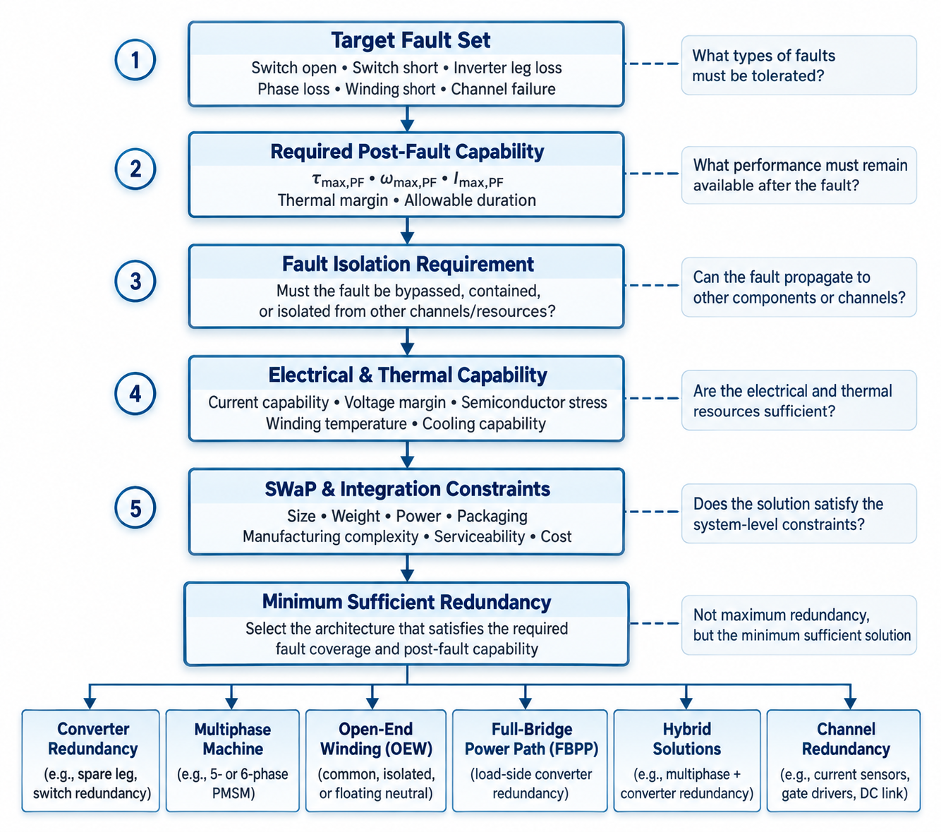
Fig. 3: Requirement-driven selection process for fault-tolerant humanoid joint-drive architectures. Topology selection starts with the target fault set and required post-fault capability. It then considers isolation needs, electrical and thermal constraints, and SWaP limits before selecting the required redundancy level.
This workflow does not replace existing fault-tolerance methods and is not proposed as a new industrial standard. Instead, it combines key design considerations reported across the fault-tolerant drive literature and adapts them to humanoid joint actuators.
The first step is to define the target fault set. A drive designed for a single open-switch fault may need a very different architecture from one that must contain winding short circuits or survive the loss of a complete converter channel.
The second step is to define the required post-fault operating envelope. Depending on the application, acceptable operation may range from reduced continuous torque to near-nominal performance for a limited recovery period. Therefore, fault tolerance should be specified by the required actuator capability, and not by a general statement that operation continues.
The third step is to consider fault isolation and fault-domain independence. For converter-level open-circuit faults, electrical reconfiguration may be enough. However, containing winding short circuits may require additional machine-level separation and lower coupling between fault domains [7].
The fourth step is to check whether the remaining electrical and thermal resources can support the required post-fault condition. Current capability, voltage margin, semiconductor stress, winding temperature, and cooling capacity determine whether a theoretically possible torque level can be sustained in practice.
Finally, the selected redundancy level should be evaluated against SWaP, manufacturing complexity, integration effort, and serviceability. The best architecture is therefore not necessarily the one with the most redundancy. It is the one that provides the required fault coverage and usable post-fault capability with the lowest acceptable system-level penalty.
7 Conclusion
Fault-tolerant electric-drive design for humanoid joint actuators should begin by defining the required behavior after a fault, not by selecting a converter or machine topology. The first step is to identify the target fault set. Faults such as switch open circuit, inverter-leg failure, phase loss, winding short circuit, and complete channel failure create different electrical and thermal conditions. Therefore, each fault class may require a different combination of protection, isolation, reconfiguration, and redundancy.
A second key requirement is to define the post-fault operating envelope. An actuator that can still rotate after a fault is not necessarily fault tolerant in a useful sense. The relevant measure is its remaining controllable capability, including available torque and speed, current limits, thermal margin, and the duration for which degraded operation can be sustained. This capability-based view supports a more realistic evaluation of humanoid fault-tolerant architectures because actuator limits directly affect robot-level motion and stability.
Finally, redundancy must be evaluated in the context of the complete actuator system. Additional power paths and fault-tolerant structures can improve fault coverage, but they also increase component count, cooling needs, packaging complexity, manufacturing effort, and Size, Weight, and Power (SWaP). In addition, redundancy provides meaningful protection only when the intended independent paths are sufficiently separated from shared resources and common-cause failures.
Therefore, the goal of fault-tolerant joint-drive design should be to identify the minimum sufficient redundancy needed to maintain the specified post-fault capability within acceptable electrical, thermal, integration, and product-level constraints. In this context, the best architecture is not necessarily the one with the most redundant elements. It is the one that provides the required fault coverage and usable post-fault performance with the lowest overall system penalty.
8 References
[1] C. Semasinghe et al., “Design of actuators for a humanoid robot with anthropomorphic characteristics and running capability,” Actuators, vol. 14, no. 5, Art. no. 243, 2025.
[2] M. Chignoli, D. Kim, E. Stanger-Jones, and S. Kim, “The MIT humanoid robot: Design, motion planning, and control for acrobatic behaviors,” in Proc. IEEE-RAS Int. Conf. Humanoid Robots (Humanoids), 2021, doi: 10.1109/HUMANOIDS47582.2021.9555782.
[3] T. Orlowska-Kowalska et al., “Fault diagnosis and fault-tolerant control of PMSM drives—State of the art and future challenges,” IEEE Access, vol. 10, pp. 59979–60024, 2022.
[4] S. Rahimpour, O. Husev, D. Vinnikov, N. V. Kurdkandi, and H. Tarzamni, “Fault management techniques to enhance the reliability of power electronic converters: An overview,” IEEE Access, vol. 11, pp. 13432–13446, 2023, doi: 10.1109/ACCESS.2023.3242918.
[5] A. G. Yepes, O. Lopez, I. Gonzalez-Prieto, M. J. Duran, and J. Doval-Gandoy, “A comprehensive survey on fault tolerance in multiphase AC drives, Part 1: General overview considering multiple fault types,” Machines, vol. 10, no. 3, Art. no. 208, 2022.
[6] B. A. Welchko, T. A. Lipo, T. M. Jahns, and S. E. Schulz, “Fault tolerant three-phase AC motor drive topologies: A comparison of features, cost, and limitations,” IEEE Trans. Power Electron., vol. 19, no. 4, pp. 1108–1116, Jul. 2004, doi: 10.1109/TPEL.2004.830074.
[7] A. M. El-Refaie, “Fault-tolerant permanent magnet machines: A review,” IET Electr. Power Appl., vol. 5, no. 1, pp. 59–74, 2011.
[8] J. Pratt, J. Carff, S. Drakunov, and A. Goswami, “Capture point: A step toward humanoid push recovery,” in Proc. 6th IEEE-RAS Int. Conf. Humanoid Robots, 2006, pp. 200–207.
[9] N. Scianca, D. De Simone, L. Lanari, and G. Oriolo, “MPC for humanoid gait generation: Stability and feasibility,” IEEE Trans. Robot., vol. 36, no. 4, pp. 1171–1188, Aug. 2020.
[10] M. Azzi, L. Baghli, C.-H. Bonnard, P. Thounthong, and N. Takorabet, “Thermal performance of fault-tolerant control strategies for a five-phase PM motor,” COMPEL—Int. J. Comput. Math. Electr. Electron. Eng., vol. 45, no. 5, pp. 850–866, 2026, doi: 10.1108/COMPEL-11-2025-0571.