
Abstract
Humanoid robots need compact electric drives that can remain controllable and produce sufficient torque after a fault. Designing fault-tolerant drives for these robots requires balancing several key factors, such as electrical independence, post-fault capability, and size, weight, and power (SWaP) constraints.
This application note examines two architectures for humanoid robot joint actuators: open-end winding (OEW) and full-bridge-per-phase (FBPP). In this article, FBPP is considered a phase-level implementation within the OEW family of architectures. The advantages and limitations of both architectures are then compared for humanoid robot applications.
1 Introduction
Electric drives for humanoid robot joints must provide the required torque and speed. At the same time, they must meet strict limits on factors such as mass, volume, power consumption, and heat dissipation. When designing fault-tolerant drives, the main challenge is not just to keep the motor running. The drive must also remain controllable and produce usable torque after specified faults. Therefore, post-fault actuator capability must be evaluated over the operating speed range, taking into account current capacity and thermal limits. Selecting a suitable drive architecture requires balancing this capability with hardware and integration costs.
Conventional three-phase drives typically use a single inverter and a star-connected machine. In this configuration, certain faults in the converter or machine can severely limit drive operation. One way to introduce redundancy is to increase the number of machine phases. This allows current to be redistributed after certain faults [1]–[3]. However, adding more phases can also increase the number of power switches, sensors, and machine connections. It can also make the control system more complex.
The open-end winding (OEW) architecture offers another way to extend converter capabilities. In an OEW architecture, both ends of each phase winding are accessible. This allows different converter configurations to apply voltage and reconfigure drive operation without necessarily increasing the number of machine phases [4]. This application note focuses on two implementations: full-bridge-per-phase (FBPP) and dual-inverter architectures. However, the connection topology alone does not determine their fault-tolerant capability. Other factors, such as the DC supply configuration, protection, fault isolation, and machine limitations, must also be considered.
This application note first explains the basic principles of OEW architectures and how they relate to FBPP and dual-inverter implementations. It then examines different DC supply configurations and their implications, along with the available reconfiguration options under different fault conditions. Finally, it summarizes the main design requirements for humanoid robot joint actuators, focusing on post-fault capability, fault-domain independence, and size, weight, and power (SWaP) constraints.
2 OEW Architecture and Converter Implementations
Open-end winding (OEW) architectures should be examined from two complementary perspectives: how the machine windings are connected to the power converters and how the converters and power supplies are configured. Both aspects influence voltage control capability, reconfiguration flexibility, and electrical dependencies within the system. However, differences in converter configuration do not necessarily imply differences in winding connection topology or greater fault-domain independence. Therefore, this section first explains the operating principle of OEW architectures, followed by a discussion of converter implementations and their engineering implications.
2.1 Open-End Winding Principle
The open-end winding (OEW) architecture changes how the machine windings are connected to the power converters. In a conventional star-connected configuration, the phase windings share a common neutral point. In this architecture, however, there is no common neutral point. Both ends of each phase winding are accessible as separate terminals. In a dual-inverter implementation, each phase winding is connected between the corresponding outputs of two inverters. As a result, the voltage applied across each winding is determined by the potential difference between its two terminals, as expressed in (1):
Vph,k = V1,k - V2,k
(1)
In this expression, Vph,k represents the voltage across the winding of phase k, while V1,k and V2,k denote the electrical potentials at the two terminals connected to the first and second inverters, respectively [4]. To apply (1), both potentials must be defined with respect to a common electrical reference. If the inverter output voltages are measured relative to their local DC-link references, the potential difference between these references must also be included in the calculation.
However, having more available voltage vectors does not automatically mean that the applied voltage can be doubled. It also does not guarantee a wider operating speed range. These capabilities depend on the DC-link voltages, the supply configuration, and the modulation strategy [4]. In addition, the supply configuration affects the electrical dependencies between the two converter sides and the common-mode voltage behavior.
Figure 1 illustrates the differences in the electrical interface between the machine and the converters in a conventional three-phase drive and an OEW architecture. In the conventional configuration, a single inverter supplies the windings connected at a common star point. In contrast, in the OEW architecture, both ends of each phase winding are connected to the converters. The voltage across each winding depends on the difference in electrical potential between its two terminals.
This change in structure allows more flexibility in voltage generation. However, the change alone does not guarantee fault tolerance. Post-fault capability depends on several factors, such as the type of fault, the ability to isolate the faulty path, the DC supply configuration, and the control strategy. Therefore, it is important to distinguish between the electrical flexibility offered by OEW architectures and their actual ability to maintain drive operation after a fault.
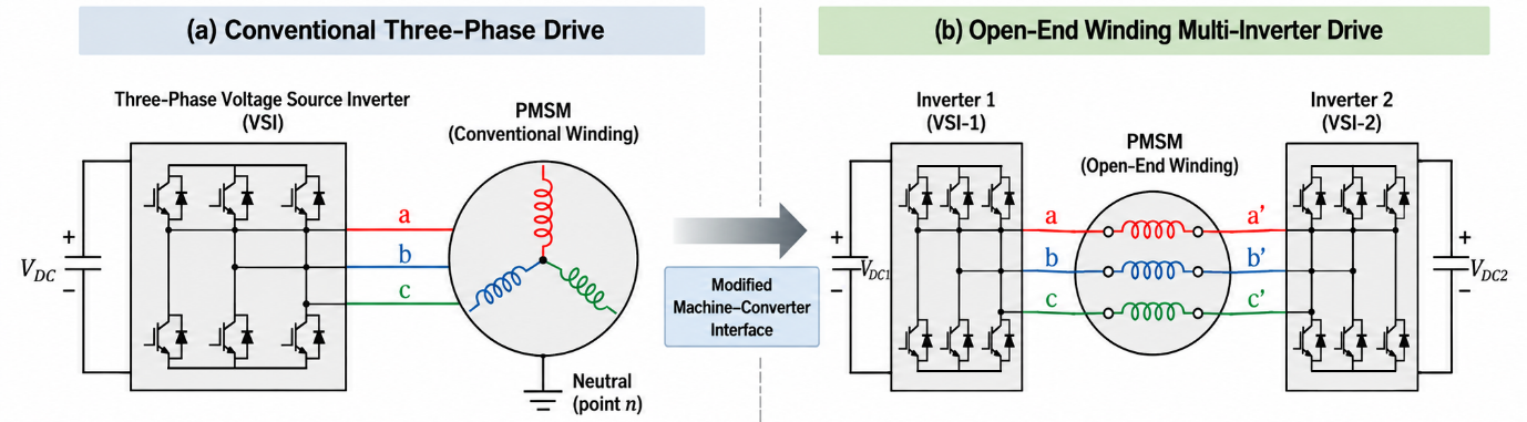
Fig. 1. Conventional single-inverter and dual-inverter OEW interfaces. OEW exposes both ends of every phase winding.
2.2 FBPP as a Phase-Wise OEW Implementation
In the full-bridge-per-phase (FBPP) architecture, each phase winding is supplied by a dedicated H-bridge. Each bridge has two half-bridge legs and four main power switches. Both ends of the winding are connected to this bridge, which acts as a dedicated power cell. This configuration allows the voltage across each phase winding to be controlled independently. It can also provide options for reconfiguring the drive after certain converter faults, provided that suitable protection and fault-isolation paths are available.
However, assigning a full bridge to each phase does not imply complete electrical independence between phases. If the bridges share a common DC bus, a fault in the power supply or in any shared DC-link component can affect several phases at the same time. Moreover, the machine windings remain magnetically coupled. As a result, a short circuit in one winding may affect the currents and operation of the healthy phases through mutual inductance. Therefore, power-cell independence, power-supply independence, and magnetic isolation are three different characteristics. Each must be evaluated separately [5].
The relationship between FBPP and open-end winding (OEW) architectures depends on how the half-bridge legs are connected to the phase windings. In a typical three-phase FBPP configuration with a common DC bus, each full bridge has two half-bridge legs. One leg is connected to one end of a phase winding, while the other is connected to the opposite end. If the first legs of all three bridges are grouped together, they form one three-phase inverter. Similarly, the second legs form another three-phase inverter. In this way, the same power circuit can be represented as two three-phase inverters, each connected to one end of the OEW machine windings [4]. Therefore, under these conditions, FBPP and dual-inverter OEW can be viewed as two different ways of representing the same power-circuit connection.
This equivalence applies only to the power-circuit connection. Other aspects may still differ, such as the DC supply configuration, modulation method, control strategy, protection devices, and fault isolation methods.For example, having two sets of inverter legs does not necessarily mean that the two power supplies are independent. Similarly, being able to apply voltage from both ends of a winding does not guarantee that every power-switch fault can be managed without interrupting operation or reducing actuator capability.
Therefore, FBPP and dual-inverter OEW architectures should be compared based on a clearly defined implementation. Their power-circuit connections may be equivalent. However, differences in hardware implementation, control, and protection can still affect their post-fault capability. This distinction is important when evaluating fault-tolerant architectures, as the number of bridges or inverters alone does not determine the degree of fault-domain independence.
For an N-phase machine, an FBPP drive requires four main power switches per phase. The same number of switches is required for a two-level dual-inverter OEW implementation:
NSW,FBPP = 4N = NSW,OEW,2VSI
(2)
In contrast, a conventional two-level voltage source inverter (VSI) uses one half-bridge leg with two main power switches per phase. Therefore, the total number of main power switches is given by:
NSW,VSI = 2N
(3)
For the configurations considered here, these expressions show that both FBPP and dual-inverter OEW architectures require twice as many main power switches as a conventional single-inverter drive. However, this comparison only considers the number of switches. The switch count alone does not determine power losses, mass, volume, reliability, or thermal performance. To evaluate these characteristics, several factors must be considered, such as device specifications, operating currents, switching frequency, modulation strategy, and cooling system design.
Figure 2 shows how the FBPP architecture is implemented at the phase level. Each phase winding is connected to its own H-bridge, and all three H-bridges share a common DC link. Table 1 compares three drive architectures: the conventional single-inverter drive, FBPP, and dual-inverter OEW. The comparison focuses on winding connections, the number of main power switches, and design priorities. This comparison shows that simply increasing the number of switches does not necessarily make one architecture better than another. Instead, the architecture should be selected based on several factors, such as controllability, common dependencies, the ability to isolate faults, and the required post-fault performance.
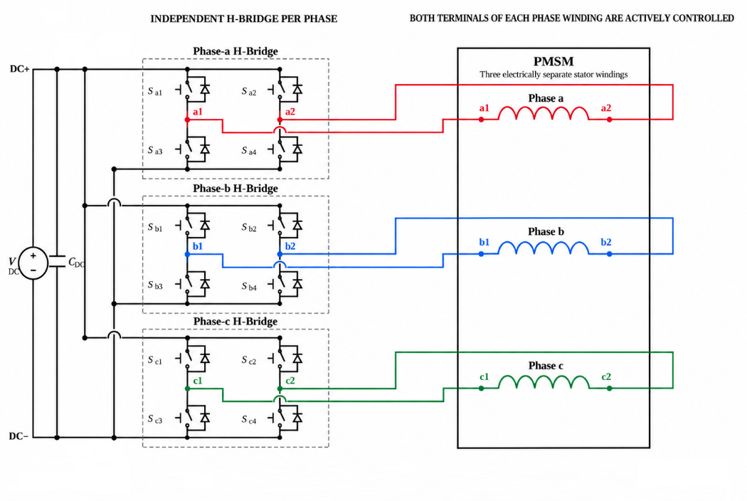
Fig. 2. FBPP phase-wise implementation of OEW. Each phase winding connects across a dedicated H-bridge. All three bridges share one DC link.
2.3 Dual-Inverter Implementation
In a dual-inverter OEW implementation, the grouping of power converter legs defines only part of the converter architecture. To fully describe the electrical configuration of the drive, the DC-link connections and the relative electrical potentials of the two converters must also be specified. This distinction is important because identical winding connections do not always mean that circulating currents have the same paths. The conditions for energy exchange and the common dependencies on the supply side may also be different [4].
Therefore, evaluating a dual-inverter implementation requires consideration of both the power-circuit topology and the power supply architecture. Section 3 examines different DC-link configurations and their implications for electrical behavior, control requirements, and power-supply independence.
3 DC-Source Configurations
In a dual-inverter OEW implementation, three common configurations can be used to supply the converters: a common DC bus, two isolated DC buses, and a floating-capacitor-based configuration [4]. As illustrated in Figure 3, the winding connections on the machine side remain the same in all three configurations. The main difference lies in how the DC links are arranged and how power is supplied to the two inverters.
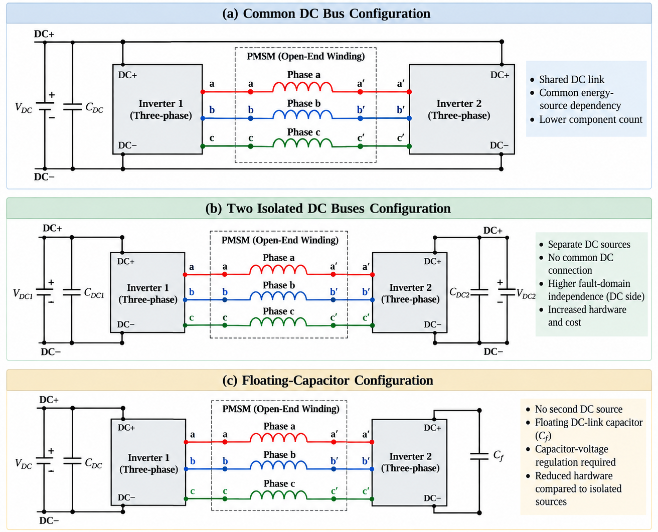
Fig. 3. OEW DC-link options: common bus, isolated sources, and a floating-capacitor link.
Figure 3 compares these three configurations. The following subsections examine each configuration. They explain how the power supplies are arranged, what dependencies are shared, and what design factors must be considered.
3.1 Common DC Bus
In this configuration, both inverters are supplied by a single DC source and share the same DC supply rails. Eliminating the need for a second independent power supply reduces the number of components on the supply side and simplifies system integration [4]. However, this simplicity introduces a common dependency in the power supply system. A fault in the DC source, supply rails, or DC-link capacitor can affect both converters at the same time. This can happen even if one of the inverters is still internally healthy.
From an electrical perspective, the common DC bus can provide a path for zero-sequence circulating currents. These currents must be controlled using the modulation strategy. Otherwise, they can cause additional losses and affect the electrical performance of the system [4].
Therefore, when selecting this configuration, the main question is whether the target fault set includes faults in the shared DC source or DC link. If the drive must maintain its post-fault capability under such faults, having two inverters alone is not sufficient. Appropriate measures must also be provided to isolate faults on the supply side or establish an alternative path for energy delivery.
3.2 Isolated DC Buses
In this configuration, each inverter has its own isolated DC link. This isolation can limit the direct propagation of certain electrical faults from the DC side of one channel to the other [4]. However, having two isolated DC links does not necessarily mean that the fault domains are completely independent. Both channels may still depend on shared upstream components, such as the battery, power supply converter, controller, cooling system, or electrical connections. Therefore, assessing fault-domain independence requires consideration of the entire power supply chain and all shared components, rather than focusing only on the separation of the two DC links.
In addition to meeting isolation requirements, using separate DC sources requires proper control of power flow. It is also necessary to prevent voltage imbalance between the DC buses. In dual-source architectures, these issues must be addressed through appropriate control and protection strategies to prevent conditions such as excessive voltage rise on one DC bus from limiting converter operation [4].
However, providing separate DC sources and the necessary isolation hardware increases mass, volume, cost, and integration complexity [6]. Therefore, this architecture is justified when DC-side isolation is a specific fault-tolerance requirement. In addition, the benefits of this isolation must outweigh the extra hardware and control costs. Even in this case, the actual independence of the two channels must be verified by examining common dependencies and potential fault propagation paths.
3.3 Floating-Capacitor Link
In this configuration, one inverter is supplied by the main DC source, while the DC link of the second inverter relies on a floating capacitor [4]. This arrangement can eliminate the need for a second independent DC source. However, a capacitor differs fundamentally from an independent power supply. It stores and releases energy, and its ability to support operation is limited by the available stored energy and the allowable voltage variation.
As a result, the capacitor voltage changes according to its energy balance during operation. Drawing energy from the capacitor to supply the converter can reduce its voltage, while energy returned to the capacitor under suitable operating conditions can increase it. Therefore, the control strategy must manage several functions, such as charging and discharging the capacitor, regulating the DC-link voltage, and controlling the system's behavior during transients [4]. If the capacitor voltage moves outside its allowable range, the operating capability of the associated inverter may be limited.
From a design perspective, the suitability of this configuration depends on whether the capacitor can support the expected energy requirements and power variations within the allowable voltage range. Therefore, this architecture should be selected based on several factors, such as energy storage capacity, allowable voltage variation, and intended operating conditions. The decision should not be based only on the fact that a second DC source is not needed. Although this arrangement requires less power supply hardware, it also requires more complex control to balance energy. In addition, this arrangement alone does not guarantee that the power supplies are independent or that the drive can continue operating after a fault.
4. Fault Coverage and Post-Fault Reconfiguration
The open-end winding (OEW) architecture alone does not guarantee fault tolerance. The ability to continue operating after a fault depends on several factors, such as the type of fault, whether the faulty section can be isolated, and which electrical paths remain available after isolation. Therefore, a fault-tolerance assessment must identify which faults can be managed. It must also determine what mechanisms are needed to contain these faults and what level of actuator performance can be maintained after reconfiguration.
4.1. Converter Open-Circuit Faults
An open-circuit fault in a power switch or converter leg may allow continued drive operation if suitable reconfiguration is available. After such a fault, the available current paths and voltage vectors change. As a result, the control strategy used during healthy operation may no longer be suitable. To restore operation, the fault must be detected and the affected switches must be isolated. The current references must also be adjusted based on the remaining capabilities of the converter [7], [8]. However, reconfiguration capabilities demonstrated for a particular multiphase drive cannot be directly generalized to all three-phase permanent magnet synchronous machines (PMSMs) without validation. The available reconfiguration options and the resulting performance depend on several factors, such as the number of phases, the converter topology, and the machine's electrical constraints. Therefore, each implementation must be evaluated independently for the specific machine and converter.
The success of post-fault reconfiguration should not be assessed solely by whether the motor continues to rotate. The available post-fault torque depends on several factors, such as the voltage margin, the current capacity of the remaining components, and thermal limits. Therefore, post-fault capability must be evaluated based on the drive's actual voltage and current limits. The actuator's thermal operating conditions must also be taken into account.
4.2. Converter Short-Circuit Faults
A short-circuit fault in a power switch is more difficult to protect against than an open-circuit fault. This is because turning off the gate signals does not necessarily stop the current. Depending on the converter topology, current may continue to flow through antiparallel diodes or other electrical paths. Therefore, simply turning off the switching commands does not guarantee that the fault current has stopped. It also does not guarantee that the faulty section has been electrically isolated.
Managing this condition requires fast protection and a clearly defined mechanism for isolating the faulty path. The design must specify how the fault current is limited or interrupted and under what conditions post-fault reconfiguration can be safely performed. Until the fault path has been effectively contained, the control capabilities of the healthy inverter alone are not sufficient to ensure continued operation.
Furthermore, the reported ability of OEW drives to tolerate short-circuit faults depends on the assumptions and implementation details of each design. These include the number of machine phases, the DC supply configuration, the protection architecture, and the control strategy. Therefore, results from one study cannot be directly generalized to other topologies without examining these conditions. Short-circuit fault containment must be validated for the specific converter and machine configuration.
4.3. Winding Short-Circuit Faults
A stator winding short-circuit fault, unlike a power-switch fault, occurs within the electrical machine itself. In permanent magnet machines, the magnetic field produced by the permanent magnets remains present even after the converter is turned off. Therefore, disabling the inverter does not necessarily interrupt the current flowing through an internal winding short circuit.
The magnitude of the fault current depends on the winding resistance, self-inductance, mutual inductance, and location of the short circuit [5]. These dependencies show that the effects of the fault depend on more than just the states of the power switches. They also depend on the electromagnetic characteristics of the machine and where the fault occurs.
Neither the FBPP architecture nor the dual-inverter OEW configuration can guarantee winding short-circuit containment on its own. Depending on the target fault set and machine design, additional measures may be needed. These may include reducing magnetic coupling between winding sections, dividing the windings into independent sections, providing thermal isolation, and using suitable protection mechanisms [5].
The selection of these measures must be based on the actual machine configuration and the consequences of the target faults. In other words, increasing redundancy in the power converter should not be seen as a replacement for fault-containment measures at the machine level. This is because converter-side control and isolation do not necessarily eliminate the electromagnetic effects of a short circuit inside a winding.
4.4. Neutral-Point Reconfiguration
Figure 4 illustrates a conceptual method for reconfiguring an OEW drive after a fault in one of the inverters. In this approach, the second inverter is first electrically isolated using a suitable protection network. The open ends of the phase windings are then connected together to form a floating star point. The remaining inverter can then supply the windings in a configuration similar to a conventional star connection [8].
This reconfiguration requires switching or reconnection devices that can perform two tasks. They must isolate the faulty inverter and establish the new winding connections. Simply turning off all the inverter gate signals does not provide electrical isolation. Therefore, the protection mechanism must prevent unintended current paths through the faulty section.
Beyond establishing the new connections, the remaining inverter must be capable of supplying the required voltage and current in the reconfigured state. As a result, post-reconfiguration performance may differ from rated performance, with possible reductions in available torque and speed. Thermal limits also determine how long the actuator can operate in this condition.
Figure 4 presents only one reconfiguration concept and should not be regarded as a universally applicable solution for all OEW drives. In practice, implementing this reconfiguration depends on several factors, such as the converter topology, the protection and reconnection network, and the machine characteristics. It also depends on validating the system's behavior after a fault [8].
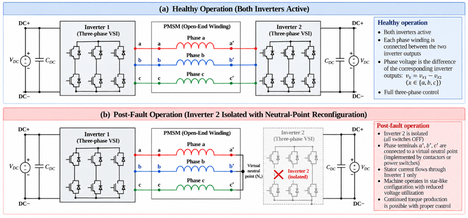
Fig. 4. Conceptual post-fault OEW reconfiguration. Inverter 2 is isolated, and winding ends reconnect to a floating neutral
5. Design Implications for Humanoid Joint Drives
Selecting a fault-tolerant drive architecture should begin by defining the target fault set and the required operational capability after each fault. Based on these requirements, the design must evaluate several factors, such as fault isolation, current and voltage limits, and thermal capacity. It must also consider dependencies on shared power sources and components. The objective is to select an architecture that meets the required post-fault performance, rather than simply increasing the number of converters or power paths.
From an implementation perspective, FBPP may be suitable for applications where phase-level control and independent organization of power cells are important. In contrast, a dual-inverter OEW implementation may be a suitable choice for designs that need more flexibility in voltage synthesis or different DC supply configurations. Both are implementation options within the OEW architecture and should not be treated as separate winding topologies. However, differences in control and protection strategies can affect their response to faults. Therefore, equivalence at the power-circuit connection level alone is not sufficient to establish equivalent fault-tolerant capabilities.
The choice of DC supply configuration should also be based on the specific system requirements. A common DC bus may be acceptable when power-supply independence is not required for the target fault set. Isolated DC links are justified when DC-side isolation is a specific design objective. Alternatively, a floating-capacitor-based DC link can reduce the hardware required for a second power supply, but introduces additional requirements for capacitor energy management and voltage regulation. In all three cases, the architectural benefits must be weighed against hardware complexity, protection requirements, and size, weight, and power (SWaP) constraints.
The guiding principle in this selection is minimum sufficient redundancy. Adding more converters or power paths does not necessarily provide greater operational value unless the target faults and required post-fault capability are clearly defined. For each target fault, the assessment must determine the torque and speed the actuator can maintain. It must also evaluate the current levels and electrical stresses on the remaining components. Finally, the assessment must determine how long the actuator can continue operating without exceeding the allowable thermal limits. Continued motor rotation alone is not sufficient evidence of useful post-fault operational capability [5], [6].
6. Conclusion
The open-end winding (OEW) architecture defines how the machine windings are connected, while full-bridge-per-phase (FBPP) is a phase-level implementation based on dedicated H-bridges. In a configuration with a common DC bus, the FBPP power circuit can also be represented as a dual-inverter OEW drive by appropriately grouping the converter legs. Therefore, these configurations should not be considered completely different winding topologies. However, differences in how they are implemented can still affect control, protection, and how the system responds to faults.
Fault tolerance in either configuration cannot be determined solely from the winding connections or the number of inverters. Instead, how the system responds after a fault depends on several factors, such as the DC supply architecture, modulation strategy, fault isolation mechanisms, and control design. Therefore, neither FBPP nor dual-inverter OEW can guarantee fault containment on its own. This capability must be evaluated and validated for the specified target faults and the actual drive implementation.
For humanoid robot joint actuators, the selected architecture must meet two requirements. It must provide sufficient fault-domain independence for the target faults while also meeting size, weight, and power (SWaP) constraints. This requires evaluating post-fault capability and coordinating the design of the electrical machine, power converter, protection system, and control strategy. Ultimately, the goal is not to maximize redundancy. Instead, the goal is to achieve the required post-fault capability with the lowest justifiable complexity and cost for the complete actuator.
References
[1] E. Levi, “Multiphase Electric Machines for Variable-Speed Applications,” IEEE Transactions on Industrial Electronics, vol. 55, no. 5, pp. 1893–1909, May 2008.
[2] F. Barrero and M. J. Duran, “Recent Advances in the Design, Modeling, and Control of Multiphase Machines - Part I,” IEEE Transactions on Industrial Electronics, vol. 63, no. 1, pp. 449–458, Jan. 2016.
[3] A. G. Yepes, O. Lopez, I. Gonzalez-Prieto, M. J. Duran, and J. Doval-Gandoy, “A Comprehensive Survey on Fault Tolerance in Multiphase AC Drives, Part 1: General Overview Considering Multiple Fault Types,” Machines, vol. 10, no. 3, Art. no. 208, 2022.
[4] M. Zerdani, S. A. E. M. Ardjoun, and H. Chafouk, “Overview of Dual Two-Level Inverter Configurations for Open-End Winding Machines: Enhancing Power Quality and Efficiency,” Applied Sciences, vol. 15, no. 10, Art. no. 5611, 2025.
[5] A. M. El-Refaie, “Fault-Tolerant Permanent Magnet Machines: A Review,” IET Electric Power Applications, vol. 5, no. 1, pp. 59–74, Jan. 2011.
[6] Y. Wang, C. Zhang, C. Zhang, and L. Li, “Review of High-Power-Density and Fault-Tolerant Design of Propulsion Motors for Electric Aircraft,” Energies, vol. 16, no. 19, Art. no. 7015, 2023.
[7] M. R. Khowja, K. Singh, A. La Rocca, G. Vakil, R. Ramnathan, and C. Gerada, “Fault-Tolerant Dual Channels Three-Phase PMSM for Aerospace Applications,” IEEE Access, vol. 12, pp. 126845–126857, 2024.
[8] A. G. Yepes, I. Gonzalez-Prieto, O. Lopez, M. J. Duran, and J. Doval-Gandoy, “A Comprehensive Survey on Fault Tolerance in Multiphase AC Drives, Part 2: Phase and Switch Open-Circuit Faults,” Machines, vol. 10, no. 3, Art. no. 221, 2022.