
Abstract
The utilization of Space Vector Modulation (SVM) in three-phase inverters is essential due to its superior DC-link voltage utilization compared to the conventional Sinusoidal Pulse Width Modulation (SPWM) method. Unlike SPWM, which is restricted to a pure sinusoidal reference, SVM inherently and intentionally injects a third-order harmonic component into the phase voltages through optimal management of switching vectors. This component is effectively eliminated from line-to-line voltages due to their differential nature, thereby overcoming voltage amplitude constraints within the linear modulation region. This structural refinement of the voltage reference extends the linear modulation range by approximately 15% compared to traditional SPWM approaches.
1 Introduction
In three-phase motor drives and inverters, output voltage quality and the efficient use of DC-link voltage are fundamental design priorities. While the traditional Sinusoidal Pulse Width Modulation (SPWM) method is straightforward to implement, it inherently struggles to fully maximize the potential of the DC-link due to its theoretical limitations. The advent of Space Vector Modulation (SVM) has transformed inverter control by offering a more advanced, digital approach. The core advantage of SVM lies in its holistic view of inverter switching states; it is more than just a pulse generation technique, it is a sophisticated algorithm that intelligently refines the phase voltage reference.
2 Sinusoidal Pulse Width Modulation (SPWM) method
SPWM is a fundamental switching technique in three-phase inverters, primarily aimed at reproducing a sinusoidal waveform at the output.
The method compares a sinusoidal reference signal with a high-frequency triangular carrier signal (Fig. 1) where the intersection points determine the precise switching instances for the power switches. Despite its simplicity in implementation, SPWM faces a significant structural challenge regarding DC-link efficiency. In classical SPWM, the maximum output voltage amplitude within the linear modulation region is inherently restricted to 0.5 (p.u.), leaving a portion of the DC-link voltage potential underutilized. This limitation directly impacts the system’s performance, as the strictly sinusoidal reference prevents the inverter from leveraging the full DC-link capacity to maximize power delivery or torque under demanding load conditions.
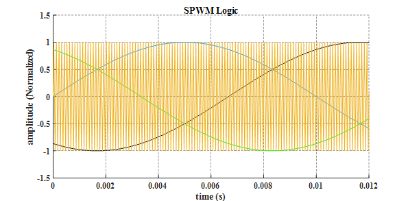
Fig. 1: SPWM Operation Principle. Three-phase sinusoidal references are compared with a high-frequency triangular carrier wave. The intersection points determine the switching instances, where each phase is controlled independently without considering the state of the other two phases.
3 Space Vector Modulation (SVM); A Holistic Vector-Based Perspective
Despite the phase-independent approach of SPWM, Space Vector Modulation (SVM) treats the three-phase inverter as a unified system. In this method, all switching states are represented as space vectors in a two-dimensional α−β plane. Rather than comparing a sine wave with a triangular carrier, SVM utilizes all permissible switching states - including six active vectors and two zero vectors - to reconstruct the target reference voltage vector. At any given moment, the desired output is defined as a rotating vector within the vector space. SVM approximates this reference vector using a linear combination of adjacent active and zero vectors within each sector of the vector hexagon (Fig. 2). A distinctive advantage of SVM is its ability to manipulate the neutral point. By optimizing the dwell time of zero vectors, SVM inherently injects a third-order harmonic into the phase voltages.
• Effect on Waveform: This common-mode component “flattens” the phase voltage, deviating it from a pure sine wave.
• Strategic Benefit: Because line-to-line voltages are differential in nature, this third-order harmonic is naturally canceled out in the final output. In return, it boosts the fundamental voltage amplitude by approximately 15%.
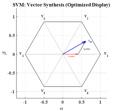
Fig. 2: SVM Operation Principle. The space vector hexagon represents all possible switching states of the three-phase inverter. The reference voltage vector is synthesized by dwelling on the two adjacent active switching vectors and the zero vectors within each sampling period, allowing for optimized utilization of the DC-link.
4 Functional Comparison of SPWM and SVM
At the edge of the linear modulation range, SPWM reaches its inherent limit at a normalized amplitude of 0.5 (p.u.), where any demand for higher voltage forces the system into saturation, degrading output waveform quality due to non-linear distortion (see Fig. 3 for line and phase voltage and FFT analysis) . In higher modulation levels the structural difference between the two methods becomes evident. SPWM suffers from “clipping” which distorts the waveform and introduces unwanted harmonics. In contrast, SVM synthesizes the reference voltage without entering non-linear saturation by leveraging intelligent switching vector management. Ultimately, the advantage of SVM lies in its ability to overcome the constraints of SPWM, extending the modulation capacity by 15% and enabling a higher output voltage amplitude relative to the available DC-link voltage (see Fig. 4 for line and phase voltage and FFT analysis).
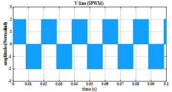
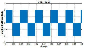
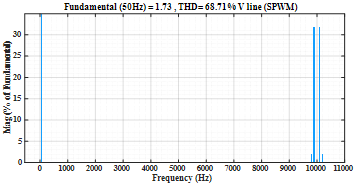
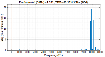
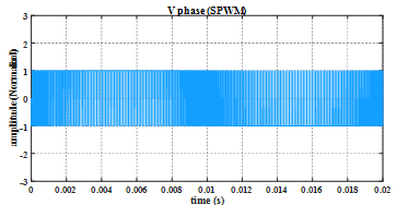
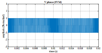
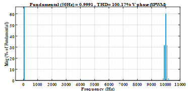
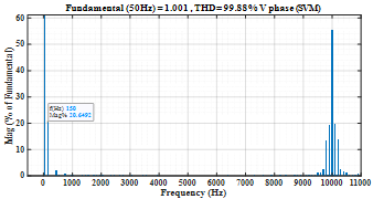
Fig. 3: Performance at the linear modulation limit (0.5 p.u.) Left: SPWM output line and phase voltage and harmonic spectra (FFT) analysis; Right: SVM output line and phase voltage and harmonic spectra (FFT) analysis both methods exhibit high-quality waveforms within this range.
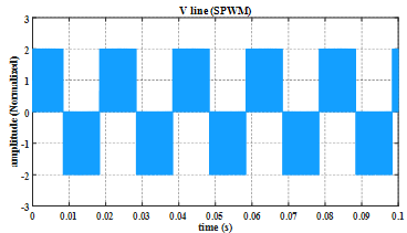
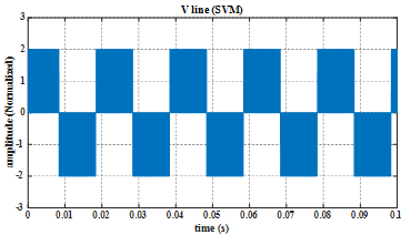
Fig. 4: Waveform distortion and harmonic content analysis under over-modulation. The plots show the “clipping” effect in SPWM (left) versus the superior voltage synthesis of SVM (right) , along with their respective harmonic spectra (FFT) demonstrating SVM’s higher fundamental amplitude and reduced distortion.
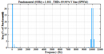
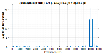
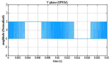
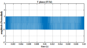
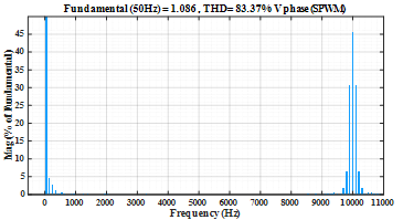
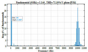
Fig. 4: Continued: Harmonic spectra comparison.